Land Sailer Tire Performance Study
;
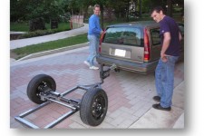
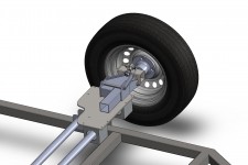
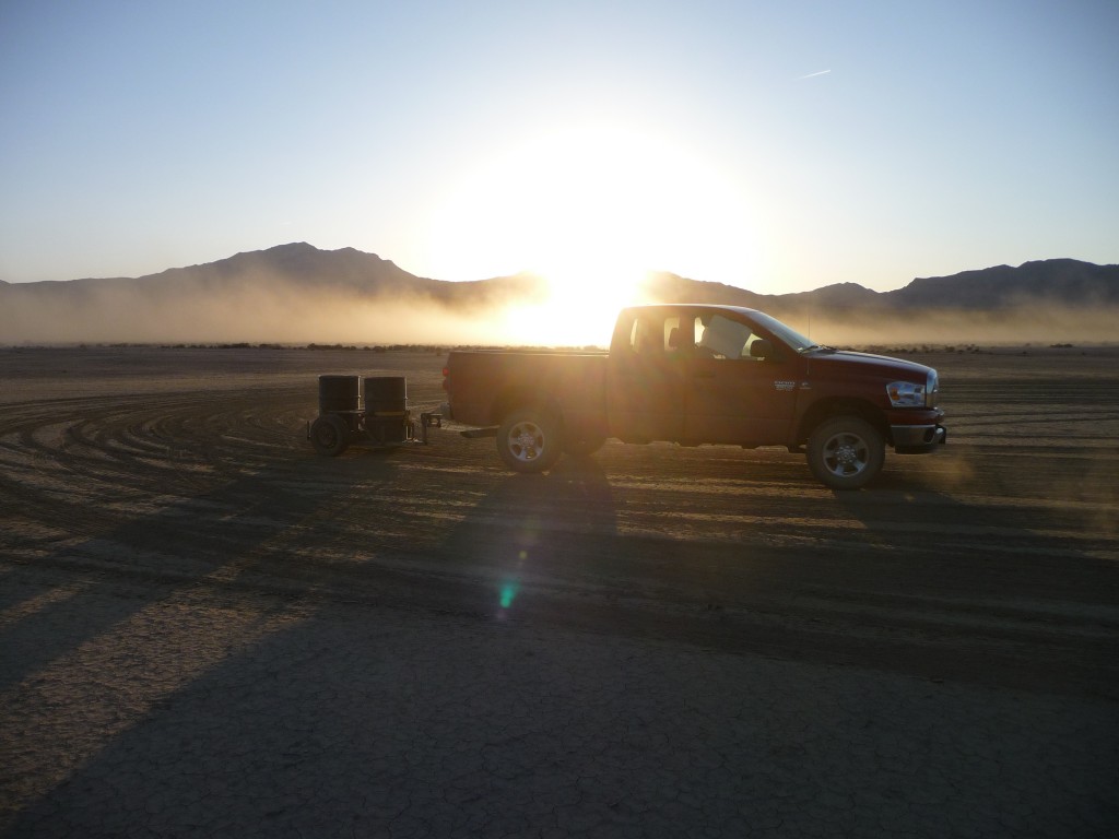
During my freshman year at Lehigh, I co-founded the Land Yacht Speed Record club with a colleague Edward Stilson, advised by Professor Joachim Grenestedt. Professor Grenestedt hypothesized that although aerodynamics are vital to the effectiveness of a land sailer, tire performance may be surprisingly important as well [1]. Because of this, our small club of engineers designed and built a tire testing trailer capable of measuring the dynamic side and drag forces developed by tires. We then conducted a week long research trip in Nevada on the dry lake bed where the speed record attempt will take place. later we were selected to present our research at a multi-university research symposium, representing Lehigh University’s mechanical engineering department.
The Physics behind a Land Sailer
Figure 1 below shows the basic forces that act on a land yacht. At high speeds, the vectors shown in figure 1 can be used to prove equation 1, also shown below. With the goal of achieving maximum speed, equation 1 shows that in the interest of maximum speed, the aerodynamic performance, defined by the sail lift/drag ratio, is just as important as the tire performance, defined by the tire side force/drag ratio. The sail lift/drag ratio of many high performance wings can exceed 40, while the side force/drag ratio of tires is much lower. Therefore, a land yacht’s tire performance, rather than its aerodynamic performance, may be a limiting factor in achieving high speeds.
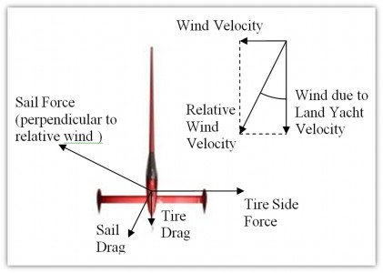 Figure 1 |
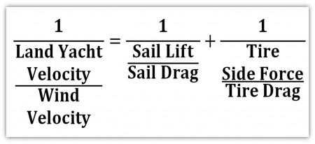 Equation 1 |
||
Measuring the Forces Acting on a Tire: The Tire Testing Trailer
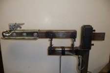
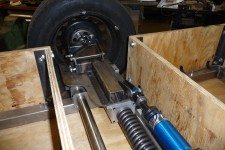
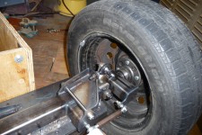
With the physics behind a land yacht in mind, a tire testing trailer was developed to measure the loads developed by tires while being pulled behind a tow car. Its features Include:
Results
Over the course of our study, a tire side force/drag ratio of 15 was consistently achieved using optimized camber angle, tire pressure, and slip angle. Under our budget and time constraints, we might assume an aerodynamic lift/drag ratio of 15 for our final land yacht. With a wind speed of 30mph, Eq. 1 gives a maximum land yacht velocity of 225mph. Although this maximum theoretical speed is not our projected speed due to the assumptions made, the tire performance that we achieved as result of this study could lead to a record breaking maximum speed.
References
[1] Grenestedt J.L. “Sailing and Equilibrium Equations.” 2/11/2008.
